Long-term bankable improvement of AEP through the use of advanced wind anemometry
One of the key points in the pre-construction and financial closure phase in the wind industry is to outline the long-term production, where the annual production degradation factor becomes critical. There is a set of measures to mitigate this degradation that includes CMSs (Condition Monitoring Systems), the use of drones with advanced optics and thermography for the care of the rotor and its profiles, as well as the use of advanced high-precision anemometry, which is the main topic to this article.
The greatest long-term impact against degradation ratios is achieved through 24-7 monitoring of the power curve, using ultrasonic spinner anemometers. Through their use we capture resource data, operation, orientation, and power curve measurement in compliance with IEC61400-12-2; i.e., making measurement equivalent to Met Mast. Any drop in production is immediately identified and perfectly traceable to wind (recorded at high frequency; 10Hz) or operating conditions. The key to this technology is that it is independent and captures the free wind.
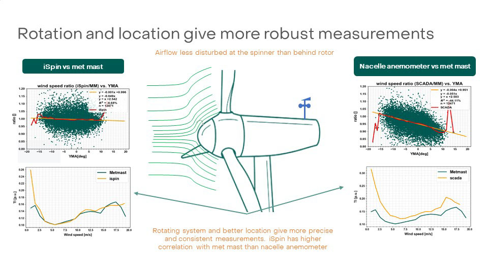
Today, measurement systems for wind turbines are not able to measure the wind exactly at the point where it hits the turbine, which is a fundamental wind measurement problem that we encounter within the entire wind industry. The latter is directly related to the fact that the turbine measurement systems themselves are located in the nacelle behind the rotor and are therefore extremely influenced by the turbulence caused by the rotor itself and other unpredictable wind phenomena. This results in inaccurate measurement of wind speed and direction, and consequently, limited possibilities for nacelle alignment, as well as an inaccurate database for performing, for example, site condition analysis and analysis of turbine performance characteristics.
Typically, nacelle anemometers or wind vanes are not capable of correctly monitoring turbulence intensity, angle, or correct wind orientation. Insufficient measurement of relative wind direction by nacelle anemometers or wind vanes can lead to yaw misalignments and, therefore, to lower energy generation and increased wear and tear on the wind turbine, resulting in higher maintenance and operating costs.
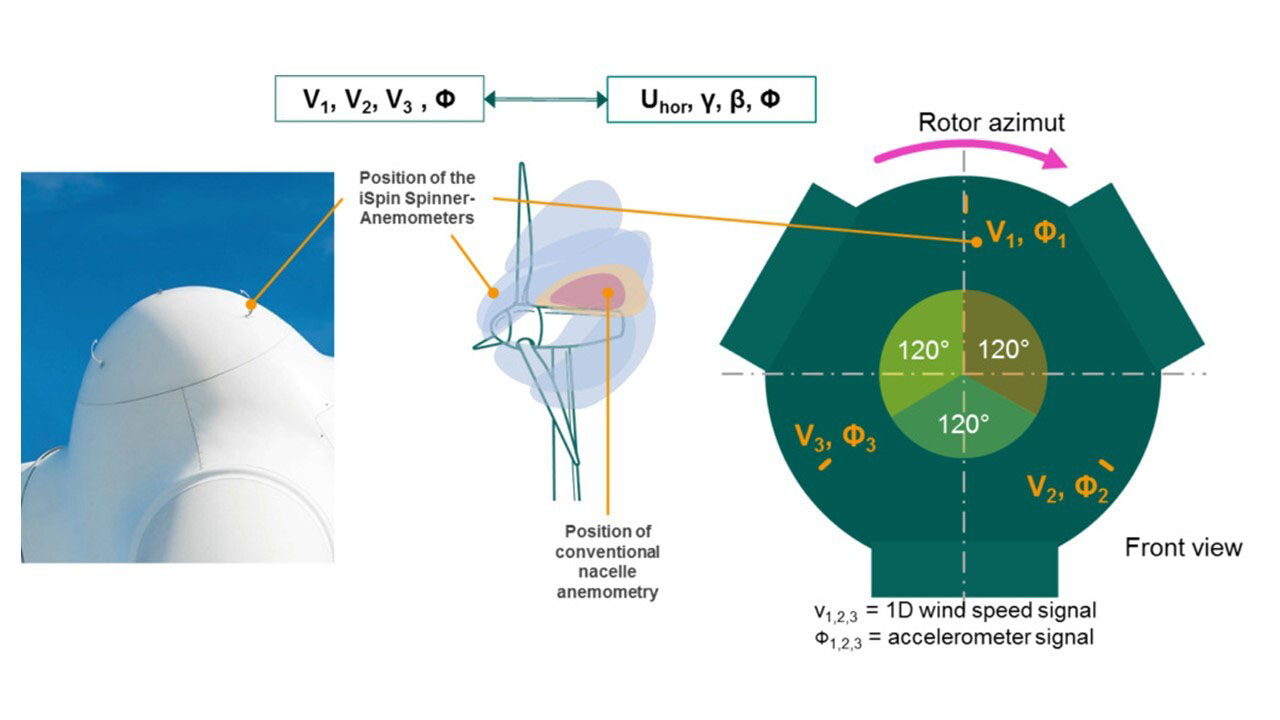
The iSpin anemometer of Nabla Wind Hub measures the wind at the spinner in front of the wind turbine rotor blades, where the flow conditions are more stable and easier to understand. Compared to the free wind speed measurement at a Met Mast, which is 2-4 diameters away, the measurement in front of the wind turbine is only affected by the shape of the spinner and a reduction of the wind speed by the rotor itself, which is referred to as the induction effect. Both effects can be easily corrected by using the appropriate calibration parameters.
This spinner anemometry technology has been verified by several independent institutions and examined in the context of evaluation projects, including DTU Wind Energy in Denmark, Vattenfall, EDPR, and other renowned independent institutions such as DNV-GL, TNO, Deutsche WindGuard and UL International.

iSpin technology – more robust measurements
The free wind speed measurement is IEC compliant and is an ideal service for independent service providers to perform power curve evaluations in accordance with IEC 61400-12-1 and 61400-12-2 guidelines.
The service provider receives the data synchronized to UTC time in 10-minute intervals, documentation for sensor calibration, including wind tunnel calibration documentation, as well as installation instructions and documentation. The service provider also receives the turbine-specific calibration factor K1 and the spinner transfer function (STF). In order to evaluate the overall uncertainty of the performance curve verification, the calculation method to determine the uncertainties for the specific wind turbine type is also provided.
Having the turbine and site-specific calibration factors of the free wind speed and the iSpin spinner transfer function, both can be used within a wind farm for turbines of the same type to carry out further performance curve evaluations. These performance curve evaluations follow the requirements and methods described in IEC 61400-12-2.
The customer receives a report on the assessment of the performance curve from an accredited expert of his choice. The definition of the content of the report is part of the contractual agreement between the customer and the expert.
The expert is responsible for the measurement of the electrical power and other turbine signals as defined in IEC 61400-12-1 and 61400-12-2. For the "measurement of a reference turbine", this is typically achieved by using independent and calibrated devices for power measurement and the time-synchronized SCADA data, which contain the information about the electrical power. For "measurements of wind farm turbines", only SCADA data that is synchronized with an Internet time server and contains information about the electrical power is used.

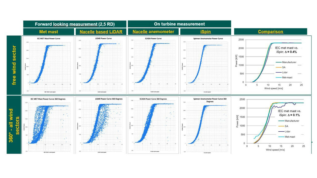
Accuracy of iSpin vs Met Mast, Nacelle anemometer and LiDAR
In this way what is obtained is a long-term power curve "guardian", which does not depend on OEM anemometry and does not penalize in cost as the use of Lidars or Met Masts, with the advantage that besides measuring the power curve, it characterizes the resource with high precision and monitors the operation and alignment of the rotor.
The performance characteristics (performance curve) per turbine are compared with the warranted manufacturer power curves provided by customers and a comparison of the theoretical annual energy yields is carried out. In the case of several wind turbines equipped with iSpin, the results of the measured quantities are shown in a wind farm report and key parameters are summarized. This analysis does not replace a power curve verification according to IEC 61400-12-2, but in combination with the site condition analysis can give important indications of the causes of deviations between actual and forecast wind turbine yields.
The methodology for data processing and power curve surveillance is as follows:
- Normalize wind speed according to IEC 61400-12-1 air density correction procedure. ADN – Air Density Normalization
- Apply horizontal wind speed and yaw angle correction to account for the yaw misalignment and terrain effect in flow inclination. YN – Yaw Normalization
- Apply turbulence intensity correction to the measured power curves according to IEC 61400-12-1:2016 to normalize all power to 10% turbulence intensity. TN – Turbulence Intensity Normalization
- Evaluate the AEP for all power curves being normalized following the steps 1 to 3 assuming a Rayleigh distribution with an annual average wind speed of 8.5 m/s according to the applicable IEC guidelines.
- Compute the anemometer Guardian power curve as the average of all 10-minute averages belonging to the power curves. This iSpin Guardian power curve and AEP will be representative of the analysed turbine type.
This technology, with its data processing and service, meets the requirements to be bankable and unlocks very relevant long-term financial model improvements, positively impacting the SPV's levelized cost of energy and long-term revenue profile.
Share on Linkedin Share on Twitter Share on Facebook Share on Whatsapp